
Building a landing platform for a drone ontop of an ATRV
The Constraints
The Test Drone: AR.Drone 2
The MERS lab has an abundance of the AR.Drone 2 from teaching a class. Additionally, the lab also has a large supply of batteries, so continuous testing can be carried out. However, the nicest feature from working with the drone is the availability of ardrone_autonomy, a ROS driver for the AR. Drone 2. The framework allows me to control, access the camera, and pull data from the drones with ROS. ardrone_autonomy also abstract the control of the drone one level. Instead of having to work telling how fast each individual rotor should spin, I could tell the drone to pitch, roll, fly higher, and fly lower.
Autonomous Landing
This was arguably one of the most important step in the entire process even though it had nothing to do with the design of the platform. Its importance comes from the fact that without an accurate and precise landing algorithm the landing platform will never be able to latch onto the drone. Without the drone being able to land accurately within at least +- 5 inches, there was no design that could accommodate for the drone.
Tag detection
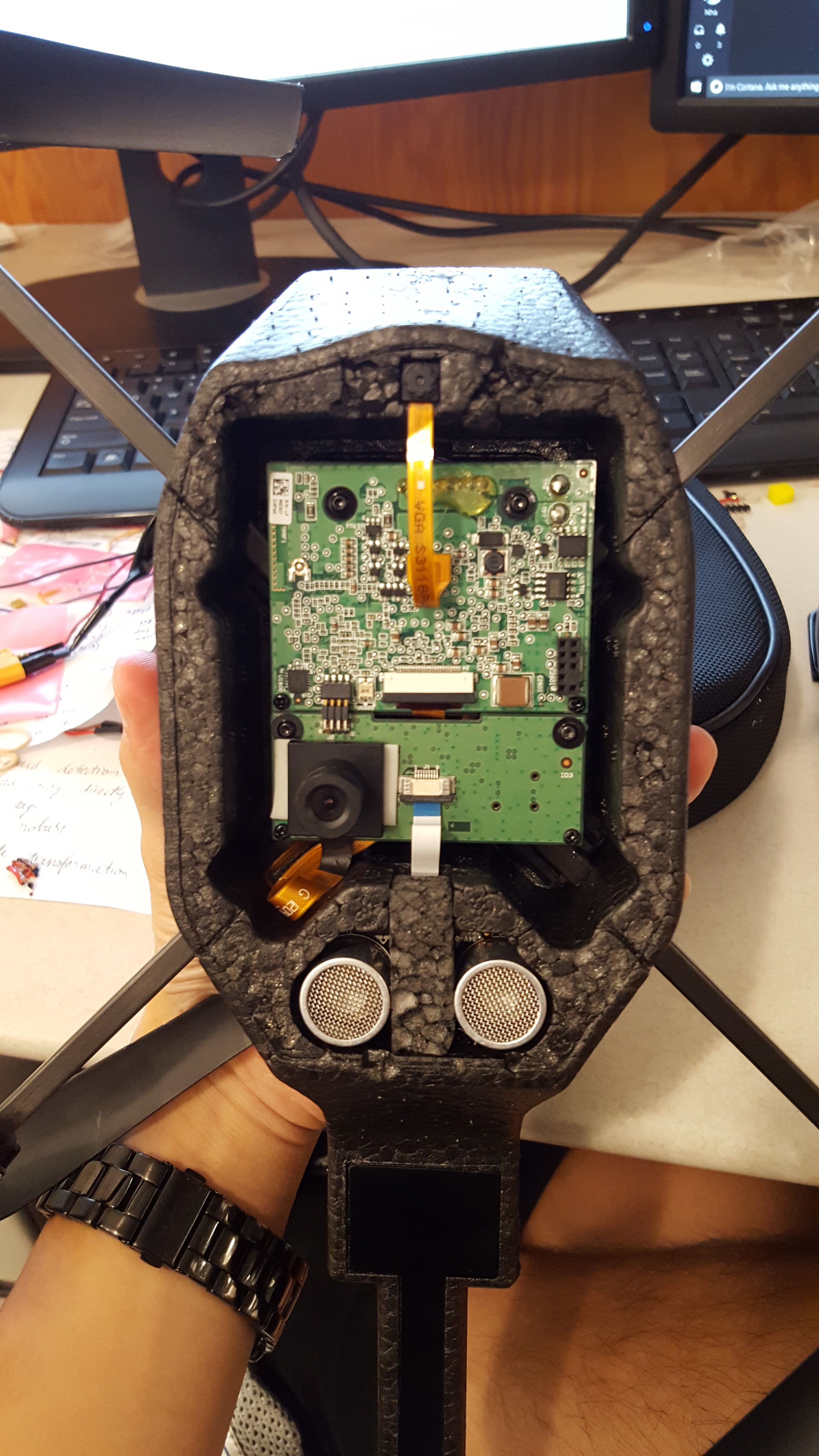
Slight Hardware Modification
For AR. Drone 2.0, it is only possible to receive image from one camera at a time. The front facing camera has a much higher resolution than the bottom facing camera. To help with the tag detection during the testing phase, the front facing camera is moved and installed next the downward facing camera.
Onboard detection
The built in detection of the AR.Drone 2 is really bad. Firstly, it was almost impossible to find an image of the detected tags on AR.Drone’s website or clear specifications on how the detection works in its documentations. I could only find the needed tags, the roundel tag, in a third party website. Secondly, the detection only works if the tag is perpendicularly facing the camera. Any slight deviation in the viewing angle will not trigger the detection. This is fatal for our purpose because the drone moves by changing its pitch and row angle, so any movement by the drone will interfere with the detection.
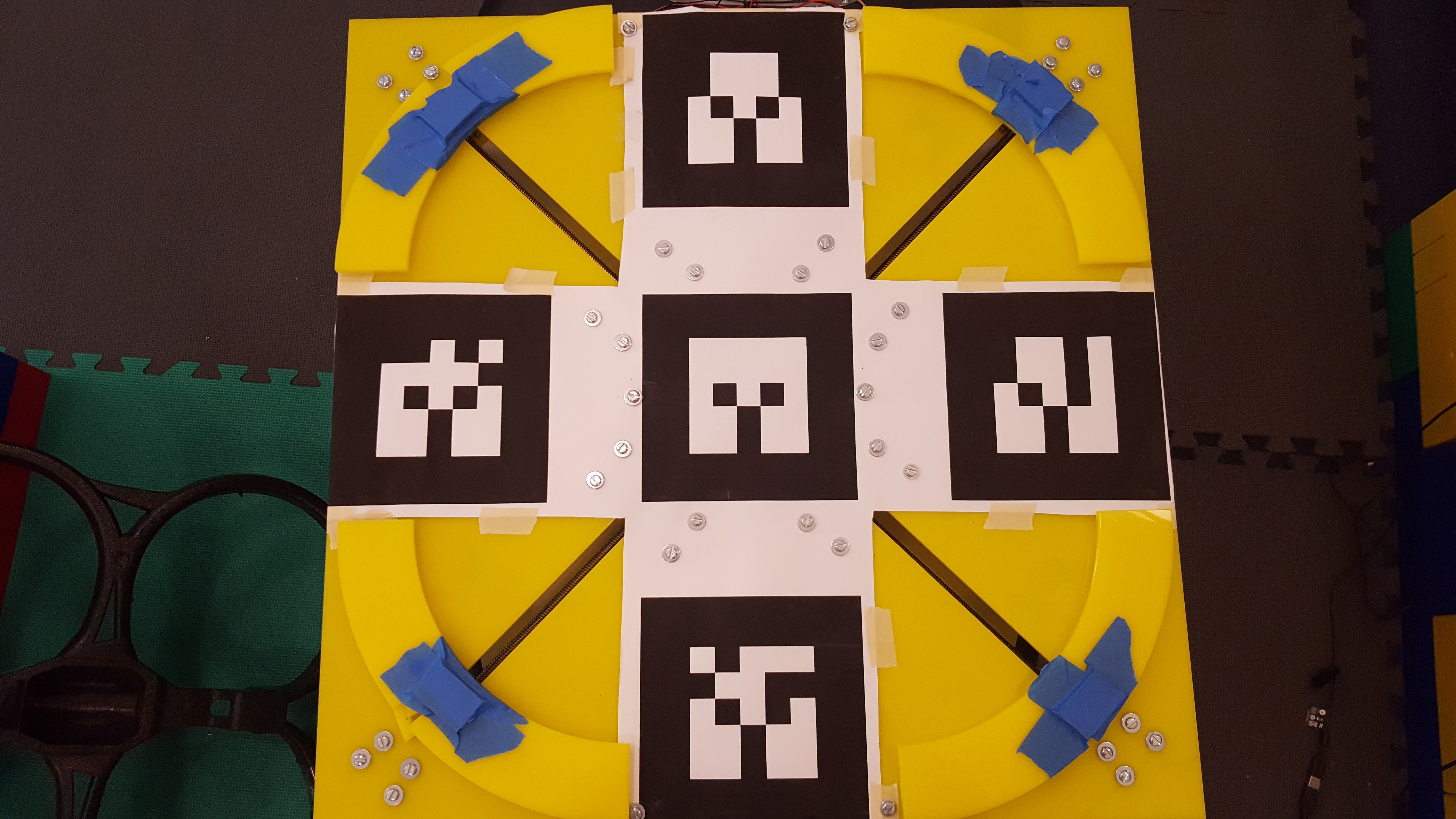
Alvar Tags
ar_track_alvar is a very sophisticated tag tracking library. It can identify and track the locations of many different tags. It’s much more robust than the onboard detection allowing it to track the tags at an angle. Two tags are used to help land the drone. One is 20x20 cm and one is 7.5x7.5 cm. The large tag allows the drone to see the target from far away. As the drone approaches the target, the large tag is too big to completely fit within the view of the camera. This is when the smaller tag comes into play.
Controller
TF
The drone moves forward/backward by changing its pitch angle, and left/right by changing its roll angle. The tag is detected to be at specific a x, y, z coordinate and orientation. In order to correspond the x,y coordinate with a roll and pitch angle, a geometric transformation must be made. ROS has a library called, tf, which automatically handles all the transformation for you once the setup is done.
PD Controller
The first immediate approach I took to controlling the drone is to use a PD controller for the roll and pitch angle. After spending many days tuning the parameters, the drone is able to quickly fly to the target. The position of the drone is right on top of the target. However, there remains a significant amount of jitteriness in the drone, quick and small changes in the roll and pitch angle. Eventually, the unstable drone spins out of control and crashes. Even after a significant amount of tuning, the shakiness remains. dx = P * (x_d-x) + D * (x’) where x_d is the desired position and x’ is the derivative of the error.
PD(DD) Controller
I came to the solution of the jittery after doing some research on the dynamic models of a quadcopter. From this paper, I came across an equation for trajectory generation on page 18.
dx = Kx,p(x_d - x) + Kx,D(x_d’ - x’) + Kx,DD(x_d’’ - x’’). where x_d is desired position, x_d’ is desired speed, and x_d’’ is desired acceleration.
This controller added another term DD for acceleration. I adopted this idea and set the desire speed and acceleration to zero. This works practically like magic and the jittery disappear even with some very rough tuning on the DD parameter.
PID Controller
As for the z axis, I utilized a standard PID controller. After tuning the parameters, it works as expected.
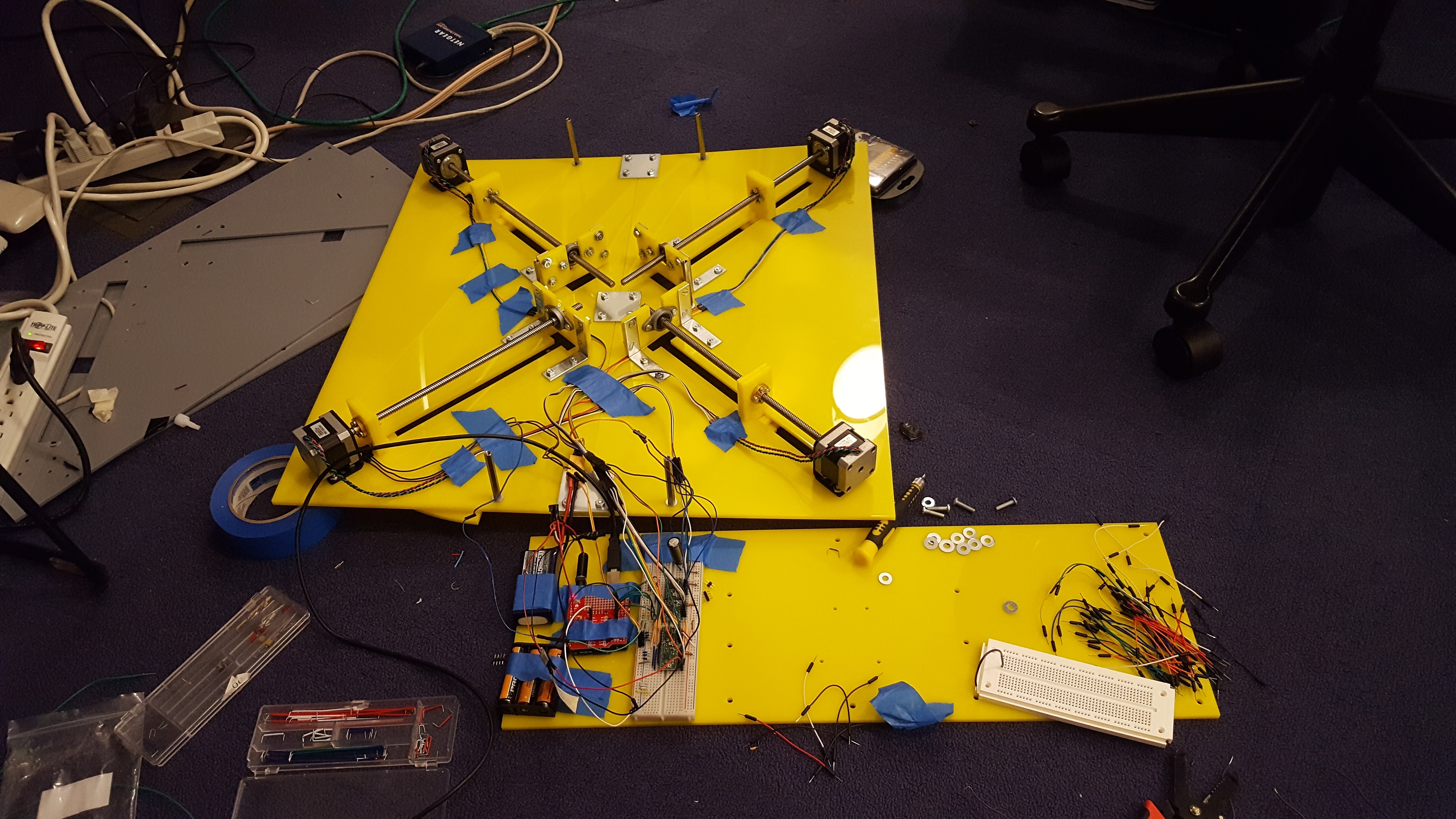
Landing Platform
The platform is designed to deal with the inaccuracy of the landing process. It can lock down the drone even if the drone land off center by +- 5 inches.
 |
 |
Here’s a video of the locking mechanism:
In action: Landing and Locking
Here’s a video of the automatic landing and locking process.