Converting my acoustic violin into an electric violin.
The Magnetic Pickup
High Level Design
There are a couple of different methods to convert an acoustic instrument to an electric instrument. For this project, I built an magnetic pickup. This is the same technology that enabled the electric guitar.
The magnetic pickup is composed of a magnet and a coil. The pickup is placed underneath the strings of a violin. It’s important to make sure that the strings are magnetically permeable i.e. steel and not gut core. As the string vibrates to make sound, a small current is induced in the string as it moves in the magnetic field of the magnet. The small induced current generates its own magnetic field. This generated field produces a voltage in the coil. As the string moves to make sound, a copy of that movement is generated as a changing voltage within the coil.
Building the pickup
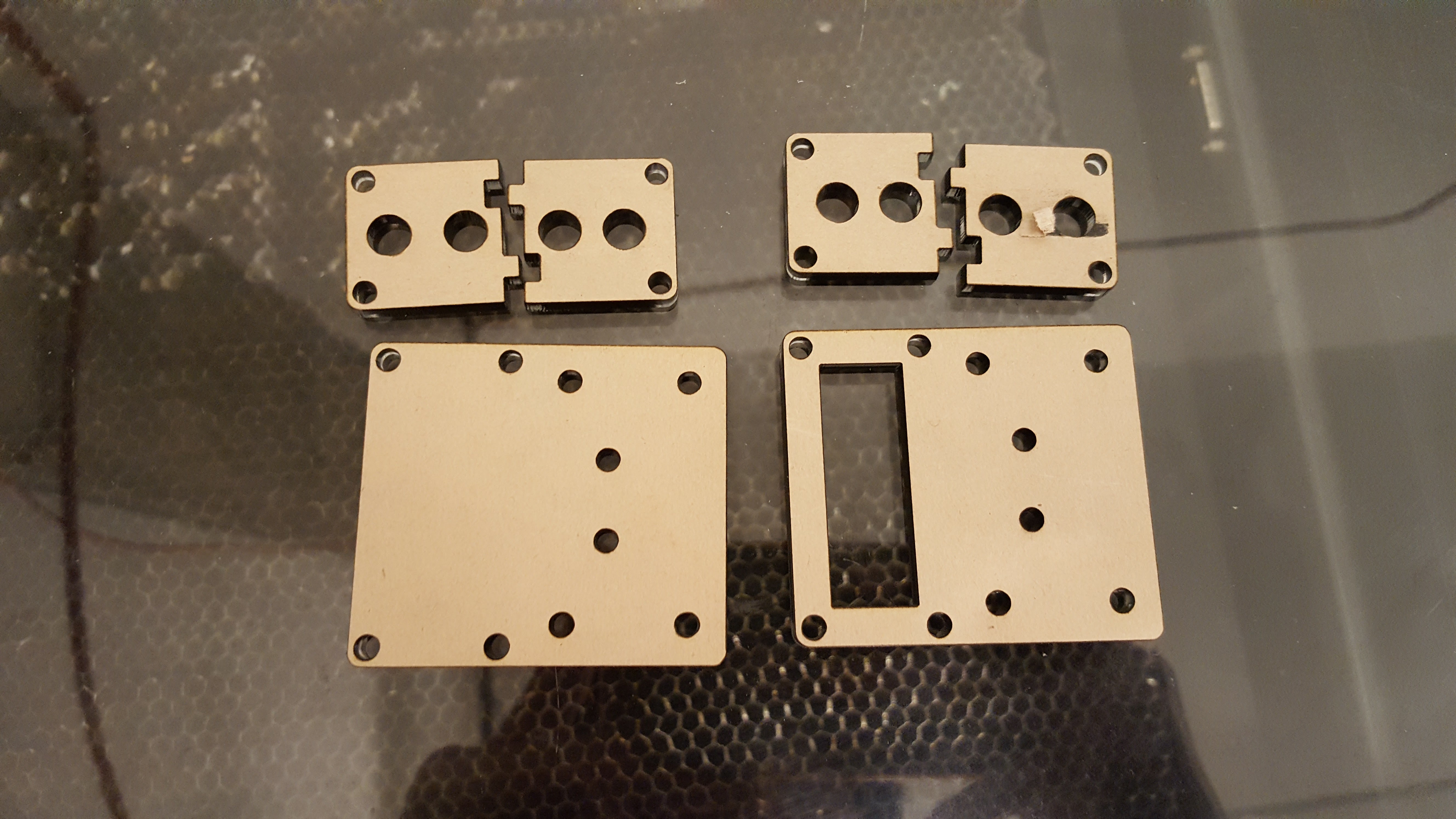
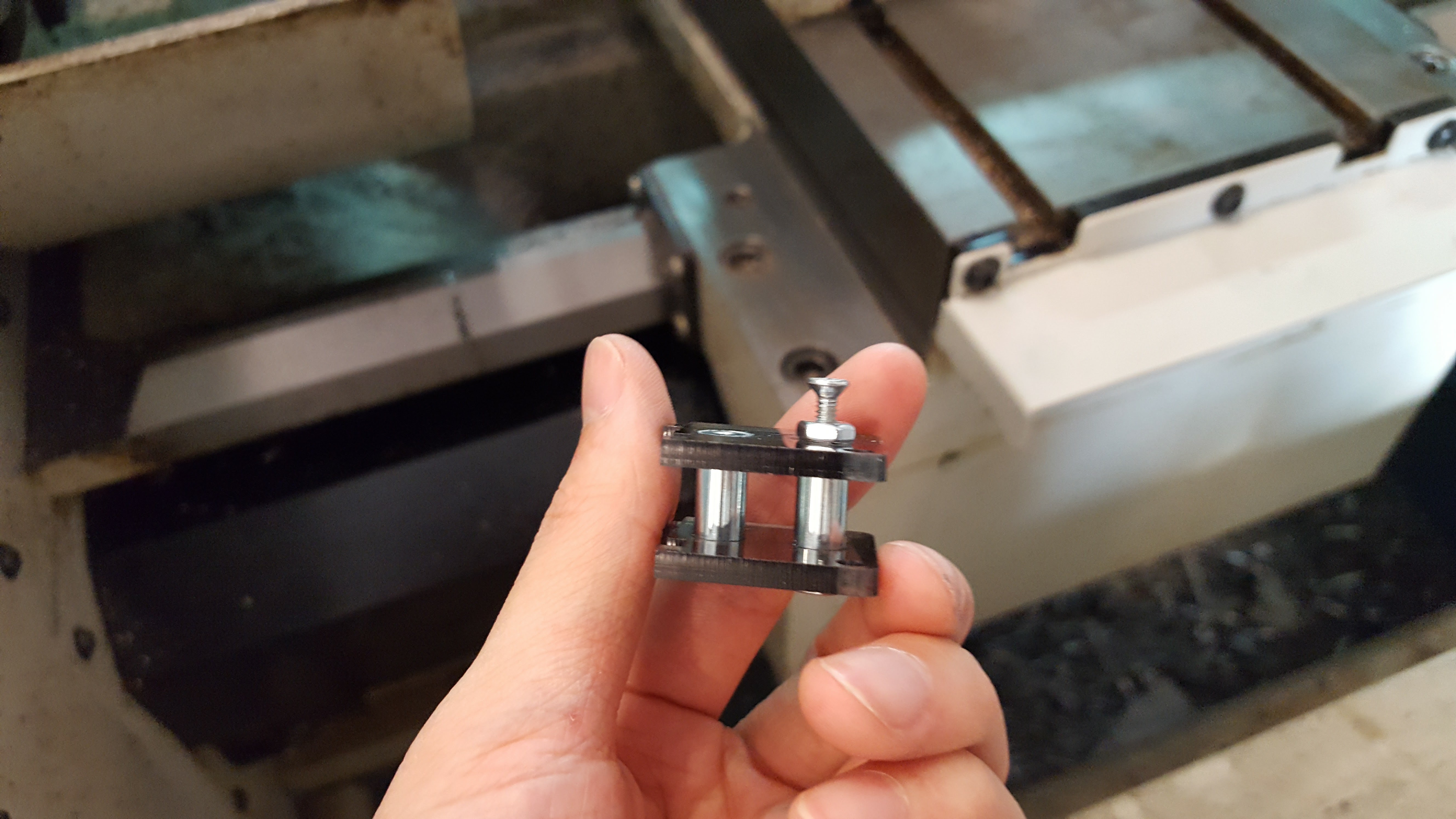
The frame of the pickup is made from laser cut acrylic and steel threaded standoffs. I had access to free acrylic, and the steel standoffs are cheaper.
 |
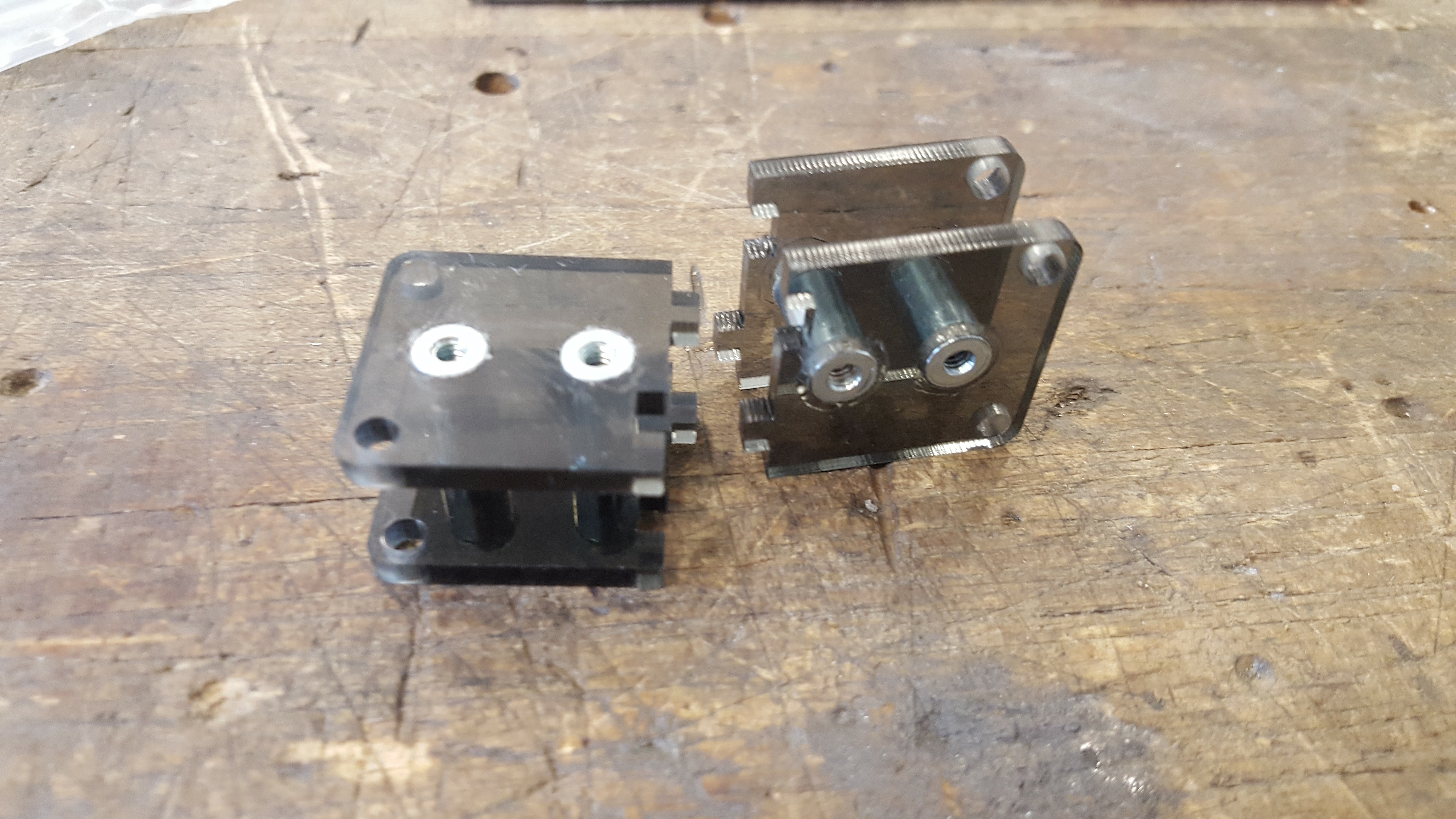 |
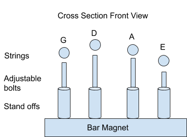
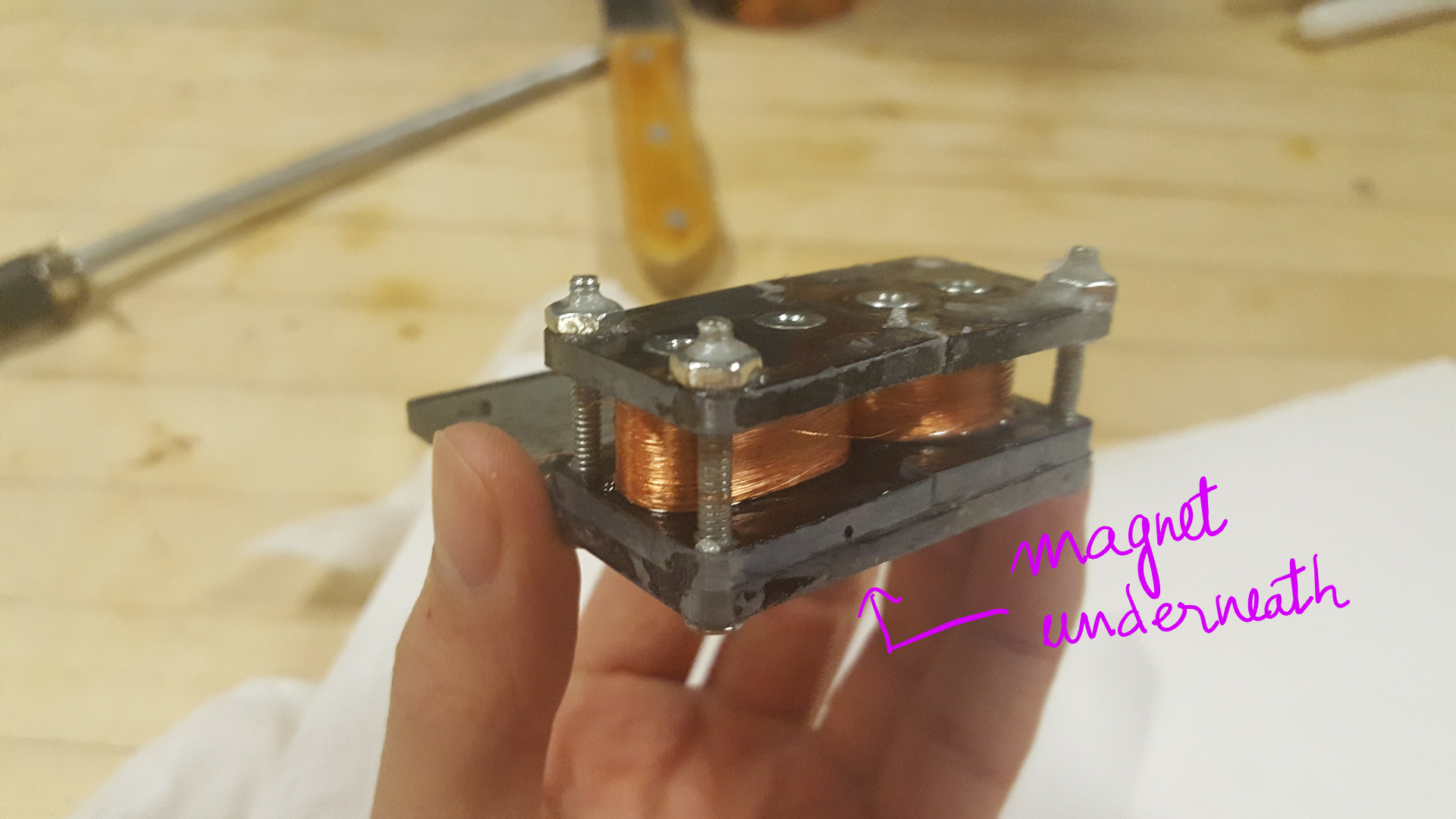
For the sound to be captured equally on each of the violin string, we need to ensure the magnet can place an equal magnetic field at each of the violin string. However, on a violin, each string has an unequal height to the body of the violin, so a simple bar magnet placed underneath the strings will not work.
To solve this issue, four threaded standoffs are placed on top of a bar magnet. Each standoff is spaced out similarly to how the strings are spaced out. A bolt is inserted into each of the standoff. It’s important that the standoffs and the bolts are magnetically permeable. The inserted bolt can adjust its own height by screwing down and up the standoff. With this setup, we can transmit the magnetic field from the bar magnet up through the standoffs and bolt. Since the bolt is height adjustable, we can ensure that an equal magnetic field is produced at each string.
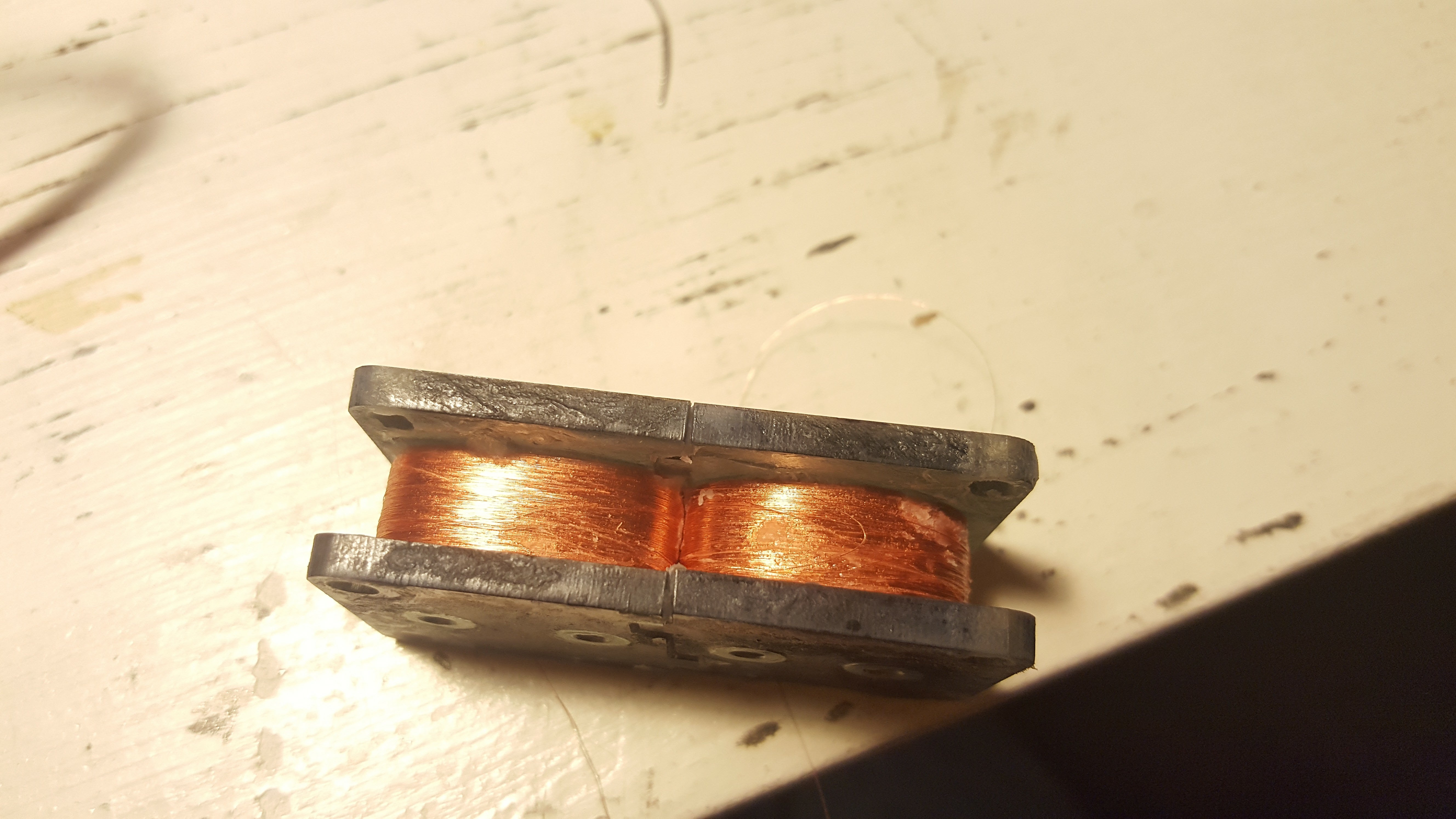
Next, two coils are wounded using thin copper wires (I forgot which gauge they were). This was incredibly frustrating as the thin copper wires can easily break and that means starting to wound the coil from scratch again. To do this step, I chuck the frame onto my hand drill and very slowly spins the frame while feeding the copper wire.
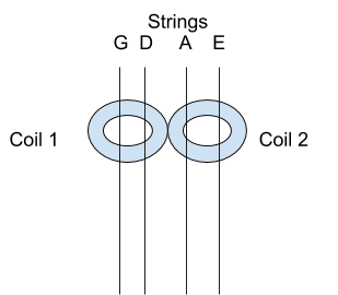
The magnetic pickup captures any stray electromagnetic wave especially the 60 Hz AC hum from any outlet. This induces a constant hum in the signal. To cancel out this common mode noise, a humbucker configuration of coil is used. Essentially, instead of one big coil capturing the signal, we used two small coils – one wounded clockwise and one wounded counterclockwise. The common mode noise appears over both coils and is attenuated. However, each individual string produces a local change in magnetic field and is not equally picked up by both coils. The violin has four strings. Under string G and D there is one coil wound clockwise. For string A and E, there is another coil underneath wound counterclockwise.
After wounding the coils, I dip the coils into melted wax. Online research informs me that without this step there will be some microphonics noises due to the coil vibrating.
 |
 |
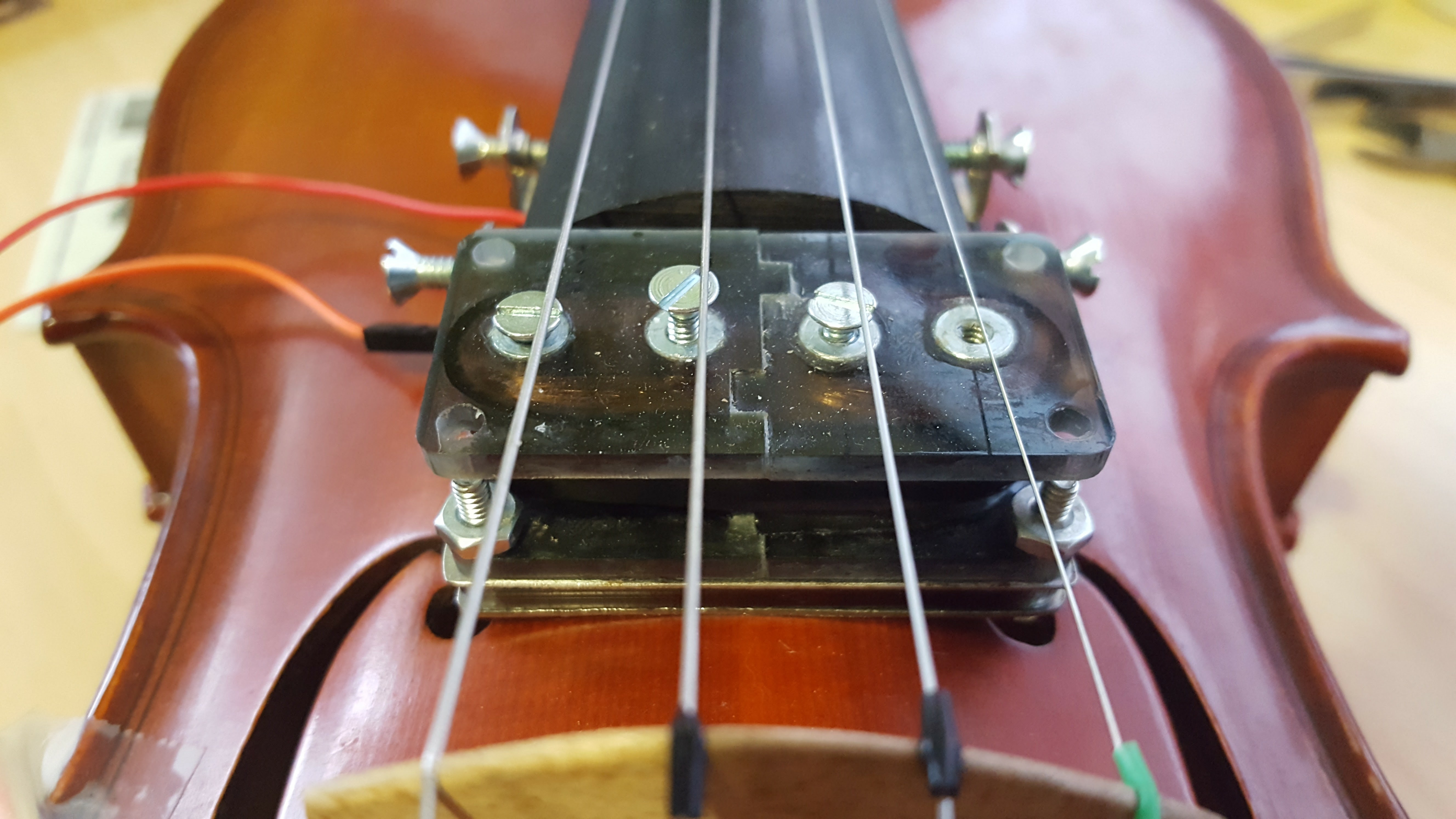
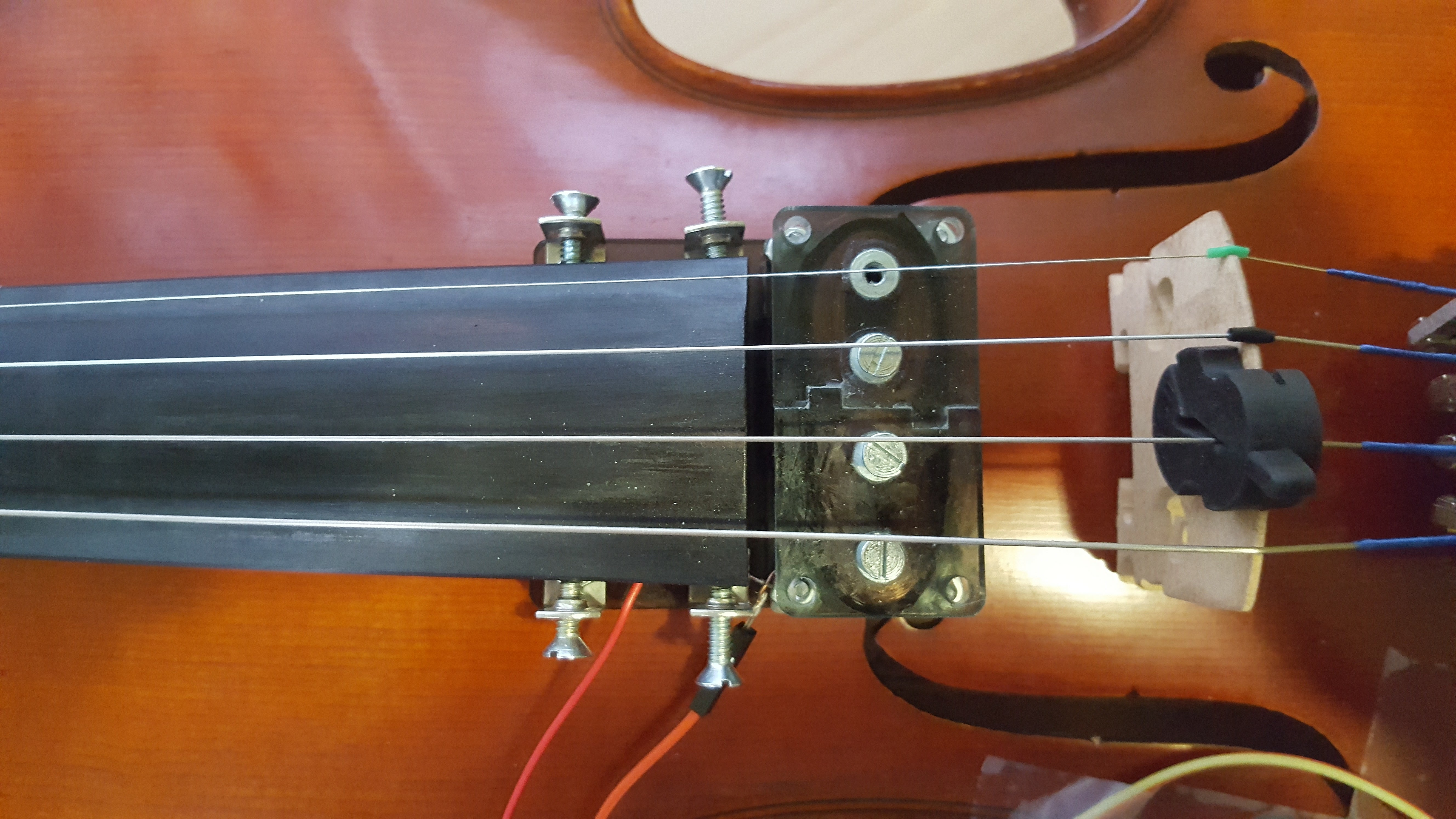
Here is the picture of the magnetic pickup fully assembled and mounted on the violin:
 |
 |
Modeling the magnetic pickup
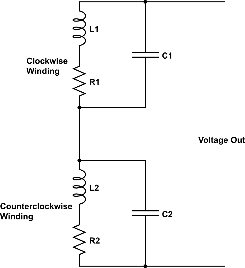
The pickup can be modeled as an LRC circuit. The coil is a loop of wires, so it will have inductance. The long length of wire needed to create the coil has resistance. Lastly, the close packing of the wires within the coil creates capacitance. This LRC circuit has self-resonance.
If the resonance is within the hearing frequency (20 - 20kHz), the voltage out would not be balanced across the full range of the violin. There would be frequencies where the sound would be louder and other softer. This brings forth a design constraint with the pickup.
The pickup cannot just have a lot of windings to have a big output, but it also has to have a small enough amount of windings to create a self resonance outside the hearing frequency. In order to arrive at the correct amount of windings, an iterative process can be taken, but due to a time constraint, I just eyeballed the number of windings based on other design. I also could have tried to model the inductance and The final design uses a N52 grade neodymium bar magnet and two coils of 4000 turns.
RLC circuit model of the pickup:
Output Result
From a rough hearing test, the higher frequencies, playing on the E string of the violin, have a slight roll off in volume. It’s noticeable softer than sounds played on the G, D, and A strings (lower frequency). The output signal at a medium playing level is 200 mV peak-to-peak. During the winding process, I accidentally missed counted, making one coil about 500 turns higher than the other one. Thus, I did not perfectly attenuated the 60 Hz AC hum. The noise signal is measured at 7 mV peak-to-peak in a normal room environment. However, the noise signal can get as high as 50 mV peak-to-peak when the magnetic pickup is near a transformer.
Preamplication Circuit
A preamplication circuit amplify and filter the signal produced by the magnetic pickup. The output of the magnetic pickup is roughly 200 mVpp. We want to boost this signal up to line level which is 1 Vrms. Next, since human hearing is only between 20-20 kHz, we want to filter to only this frequency range. Lastly, we want to give the performer more control over their instrument. The circuit also also has a tone control. It attenuates or boosts the signal of the bass frequencies (10 Hz - 1 kHz) and the treble frequencies (1 kHz - 20 kHz).
Input Conditionings
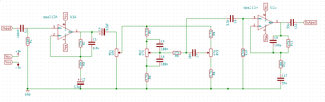
The preamplification circuit is very simple. It’s just an op-amp in a non-inverting amplifier configuration with some capacitors to act as filters. One important aspect of this amplifier is its high input impedance, R1, which is at 10 MOhms. This is important because the output impedance of the magnetic pickup is in the 10s of kOhms, so to preserve the voltage signal, we have R1 at 10 MOhms – two order of magnitudes larger than the output impedance of the pickup as is typically done for a preamplifier. With a high input impedance, the input current into the amplifier is low, so the signal will not be distorted from resistive lost.
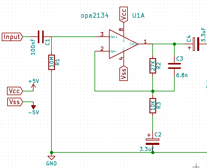
Another advantage of a high input impedance is that it will act as a voltage divider along with the output impedance of the magnetic pickup. In effect, this high input impedance also equilibrate the output signal of the pickup even if the resonance is in the hearing frequency. The over gain of the amplifier is determined by R3 and R2. As for filtering the signal, C1 controls the high pass filter and C3 controls the low pass filter.
Tone Control
The tone control is replica of an Baxandall tone control network. First, the signal is fed into the network using a potentiometer RV1. This acts as an overall volume control, so it has to be a logarithmic potentiometer. In this network, the bass is controlled by RV2, and the treble is controlled by RV3.
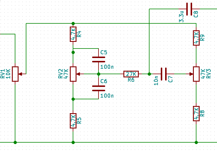
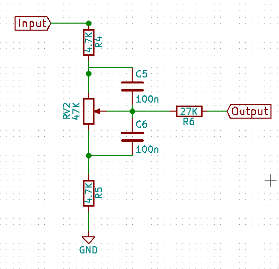
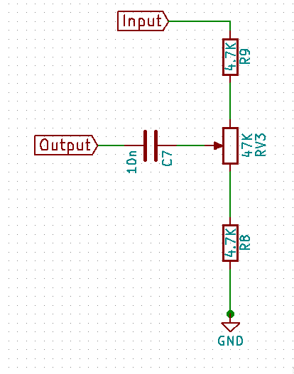
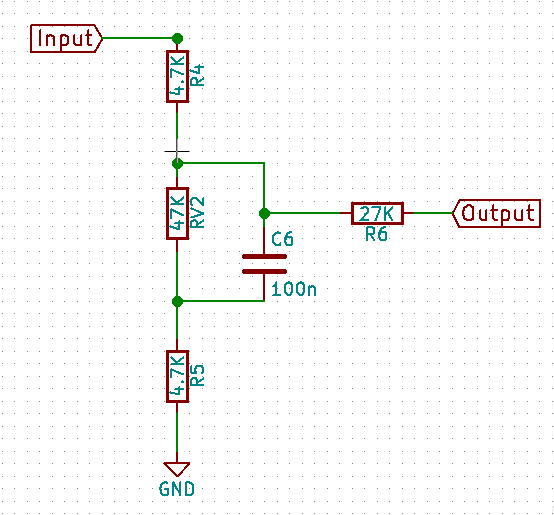
The operation of the circuit can be splitted into two parts. The left half of the circuit controls the bass response while the right half of the circuit controls the treble response. The circuit works by varying the cutoff frequency of the RC passive filter. The cutoff frequency is changed by varying the resistance of the potentiometer.
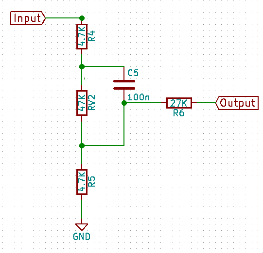
The left circuit is the bass control circuit of the Baxandall control network. The right circuit is the treble control.
 |
 |
For example, if we look at just the bass control part. On the left, we see the bass control at full boost. On the right, we see the bass control at full cut.
 |
 |
The tone control circuit is designed to set the midpoint to around 1 KHz with the two cut off frequencies to be at 10 Hz and and 100 KHz, each two decades away from the midpoint, when the potentiometer is half way turned.
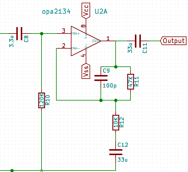
Final Amplication
Lastly, because the tone control network is a passive network, there is loss in the circuit. Thus the signal is boosted again through a non-inverting amplifier configuration. This works in the exact same way as the previous amplifier. The gains of the two amplifiers were chosen so that the output this stage would be line level or 1 Vrms.
Video
I originally started the project as a side project receiving funding from ProjX. However, the project fits within the coursework of 6.101 (Analog Electronics Lab), so I turnt it into my final project. You can see a recording of the electronic violin here with other fancy effects done by my teammates.